Adrithi
Home/Field-Driven Design
Field-Driven Design

Using fields to drive lattice and geometry changes

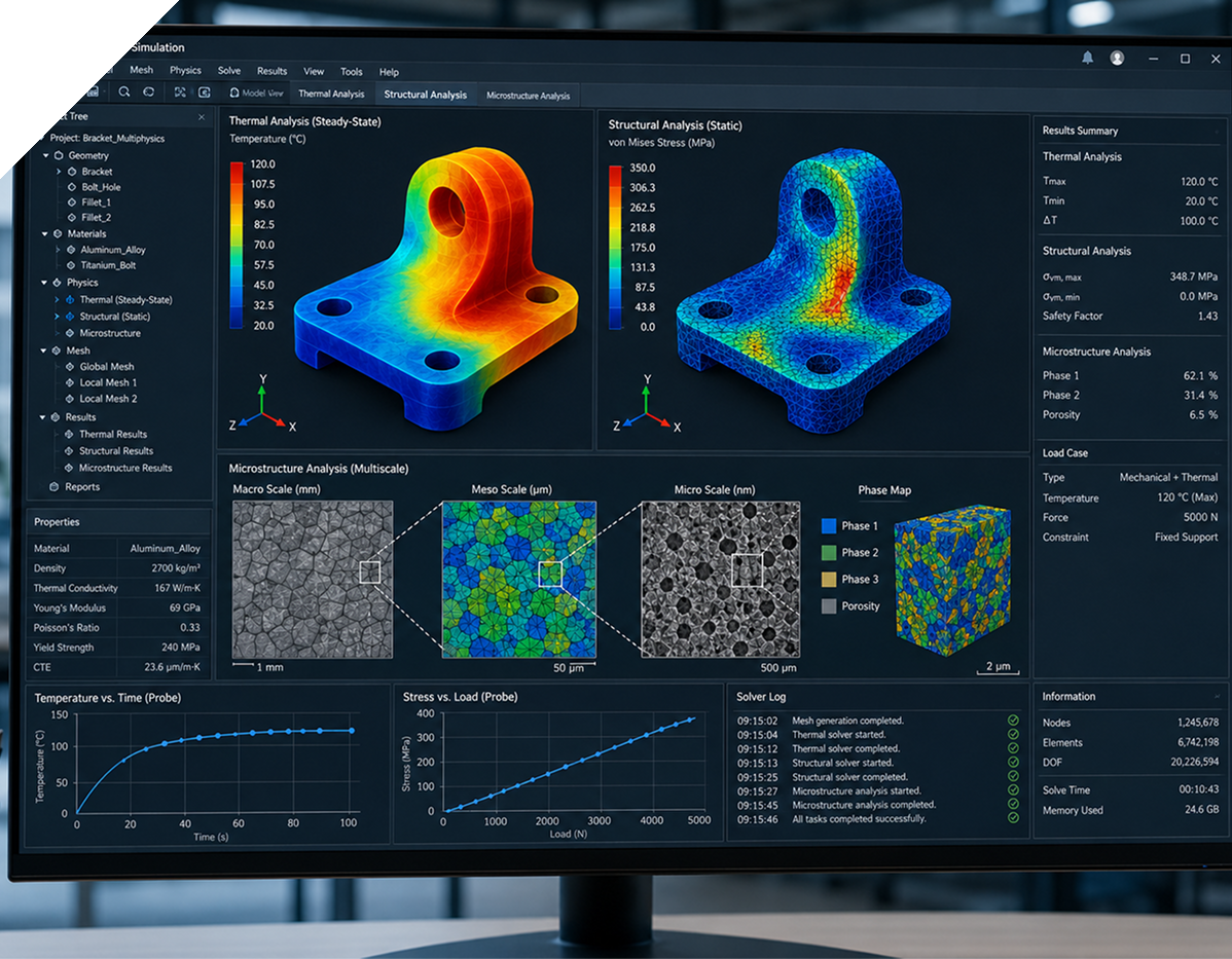
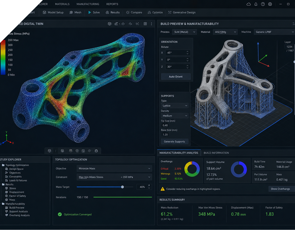
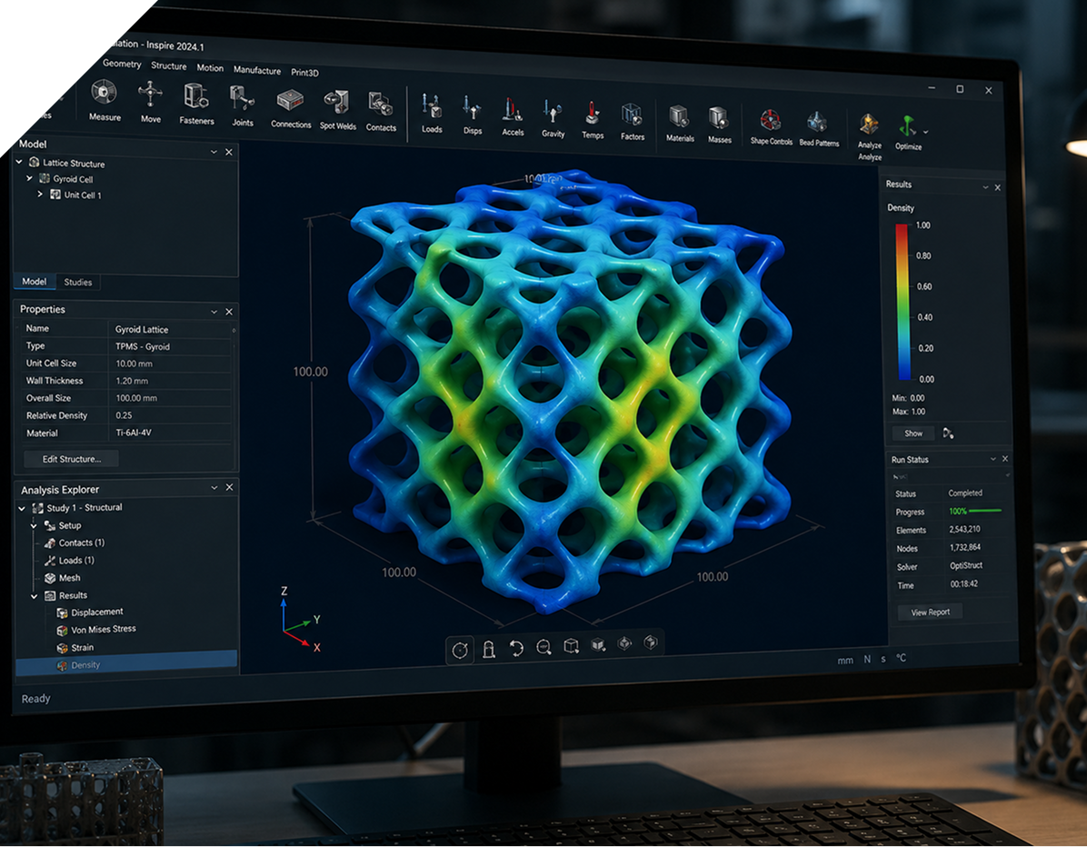
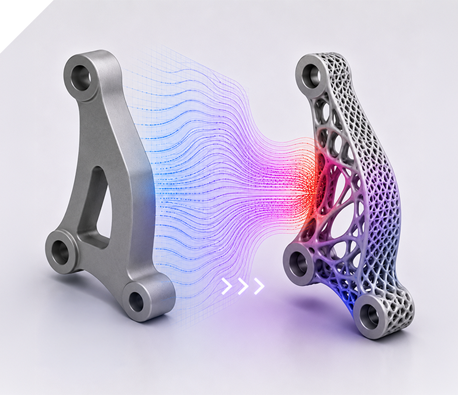
We use simulation and design fields – such as stress, temperature or distance – to vary lattice density, wall thickness and surface features within a part. The aim is to place material where it is most useful, while keeping manufacturing constraints in mind.
Lattice And TPMS Structures

Generative And Optimisation Workflows

Multiphysics And Multi‑Scale Design

Lightweighting And Advanced Manufacturing

What you can expect

Where this tends to be useful

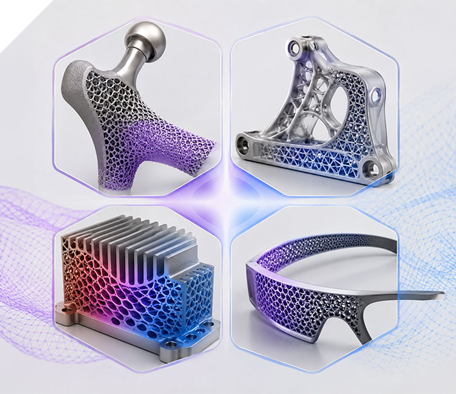
Components where weight, stiffness, heat transfer or energy absorption all matter at once – such as implants, aerospace brackets, thermal management inserts and consumer products for additive manufacturing. In these cases, uniform structures are often a compromise; field‑driven design allows for local tuning instead.

HOW WE COLLABORATE

How we position Field‑Driven Design

It is an extension of simulation‑driven design: rather than designing once and checking later, we use simulation results directly as inputs to geometry. The process stays grounded – we start from clear requirements and work back to what level of field control is appropriate.
Describe the part, manufacturing route and what you want to improve; we will outline options and effort.

Field‑Driven Design

Examples of field‑driven design work we undertake

The examples below mirror the themes from your Field‑Driven Design pillar.

Lattice and TPMS structures

Spatially varying lattices for strength, cooling and comfort

Stress‑driven lattice grading

vary cell size or wall thickness based on stress fields to support load paths while removing surplus material.

Gyroid and other TPMS structures

design continuous surfaces for implants, heat exchangers and energy absorbers with locally tuned properties.

Pattern and perforation control

use distance or functional fields to drive perforation patterns, porosity and surface texture.

Generative and optimisation workflows

Combining optimisation with lattices and shells

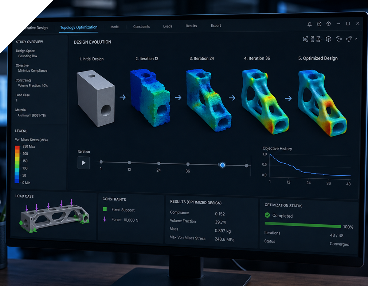
Simulation‑driven generative design

use simulation results to inform generative concepts before selecting promising options.

Single‑ and multi‑objective optimisation

balance stiffness, weight, thermal performance and manufacturability within a common workflow.

Topology optimisation hand‑off

translate topology‑optimised shapes into manufacturable lattices and shells rather than leaving them as abstract forms.

Multiphysics and multi‑scale design

Linking part‑scale performance to local features

Simulation‑driven parameterisation

use structural, thermal or flow simulations to set lattice or shell parameters across a part.

Multi‑scale considerations

connect local lattice behaviour to overall stiffness, fatigue life or heat transfer performance.

Data and material integration

incorporate material test data or process limits to keep designs realistic.

Lightweighting and advanced manufacturing

Designs ready for additive and modern manufacturing

Part and assembly lightweighting

remove mass while maintaining required stiffness and strength, guided by fields rather than uniform thinning.

Process‑aware geometry

respect build direction, support strategies and allowable feature sizes for the chosen process.

Design for both additive and conventional routes

develop concepts that can be manufactured additively today and, where needed, adapted for traditional methods.

If you are exploring lattices, lightweighting or complex geometry,field‑driven methods can help structure the work

We can start with a simple pilot part and build a reusable pattern from there.

Field‑Driven Design

How we work

The approach mirrors our CFD and FEA practices, with an emphasis on modest claims and traceable steps.

Start from the part and objectives

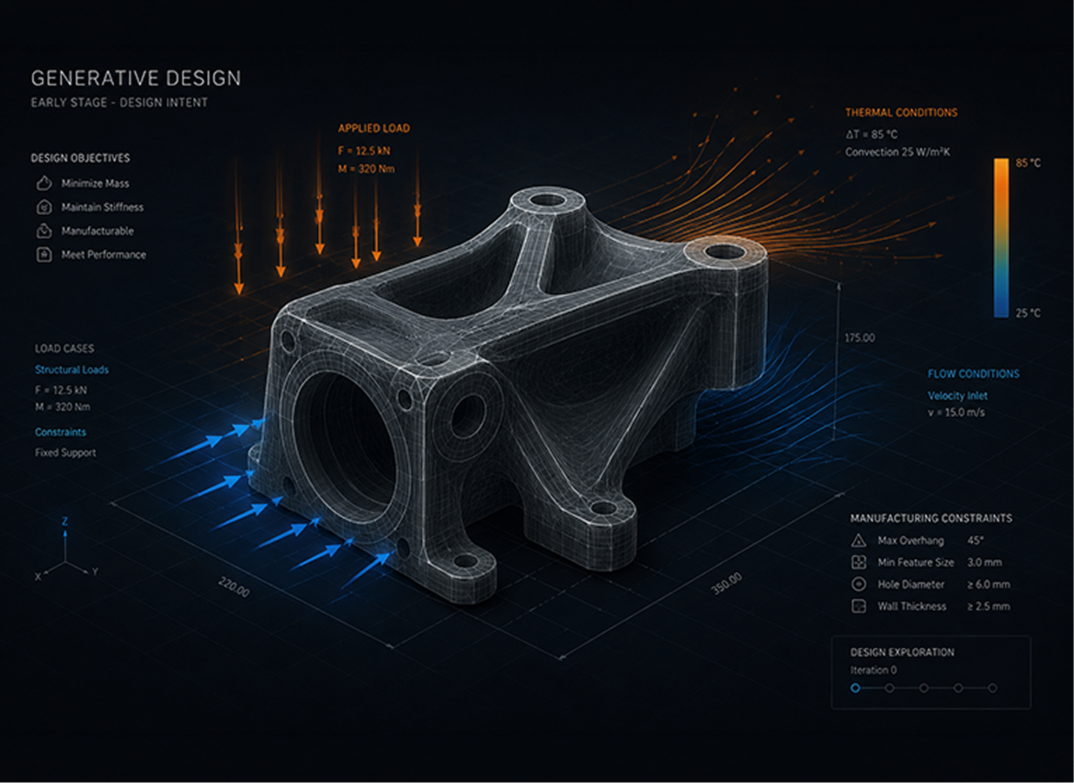
Define the part, loads, thermal or flow conditions and manufacturing constraints.

Identify which fields are most relevant – for example stress, temperature or distance.

Agree on where field‑driven variation adds value and where simpler geometry is sufficient.

Keep geometry and fields understandable

Document which fields drive which parameters, and at what ranges.

Present results as trade‑offs between weight, stiffness, heat transfer and manufacturability.

Where helpful, hand over rules and templates so your team can reuse the approach.

Curious Whether FDD Is A Fit? Share a short description or sketch of your system and we'll respond with an informal view on applicability, effort and likely value – before you commit to a full project.

PROOF, NOT PROMISES

CUSTOMER SUCCESS STORIES, BY INDUSTRY

A sample of engagements across our sectors. More case studies are being prepared as current programmes reach a publishable stage.
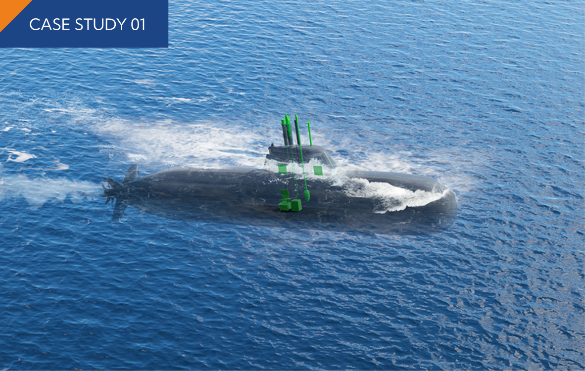
SUBMARINE MAST THERMAL ANALYSIS DLRL
DEFENCE & NAVAL

SUBMARINE MAST THERMAL ANALYSIS DLRL

Conjugate heat-transfer simulation of a submarine mast assembly, validating thermal margins for embedded electronics under sustained operational loads.
CFD · Thermal · DLRL
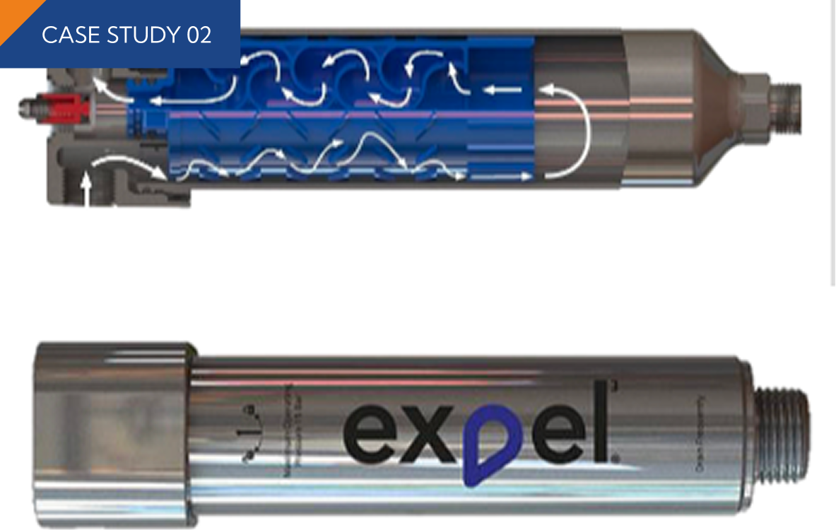
ADVANCED FILTRATION SYSTEM CFD — ERIKS UK
INDUSTRIAL & PROCESS

ADVANCED FILTRATION SYSTEM CFD — ERIKS UK

Multiphase CFD study of an advanced filtration system for ERIKS UK's Expel range, characterising pressure drop and flow uniformity across duty conditions.
CFD · Multiphase · ERIKS - UK · Expel
DATA-CENTER HVAC COOLING
AEROSPACE

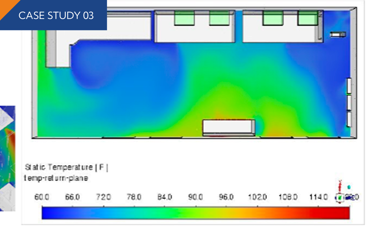
DATA-CENTER HVAC COOLING

Delivered a CFD-driven HVAC cooling assessment that verified system redundancy, optimized cooling performance, and ensured reliable operations.

HVAC

Engineering Intelligence. Proven by Physics.

Discover how AI-driven engineering simulation and multiphysics solutions solve complex challenges across defence, aerospace, marine, and industrial sectors.


Footer Background
All Rights Reserved © Adriti Techno Engineering (OPC) Pvt. Ltd.
THE SCIENCE OF CERTAINTY